Expansion Connector
OpenNMC provides a two-socket expansion connector for add-on hardware.
Mechanical Layout
GPIO: 2x15, 1.27 mm pitchCARD: 2x8, 1.27 mm pitch- The
GPIOsocket breaks out signals from the USB hub and the SoM. - The
CARDsocket breaks out unused SmartSlot signals. - Revision D uses the full
CARD2x8 socket. - Revision C uses a
CARD2x7 socket with the top UART row omitted.
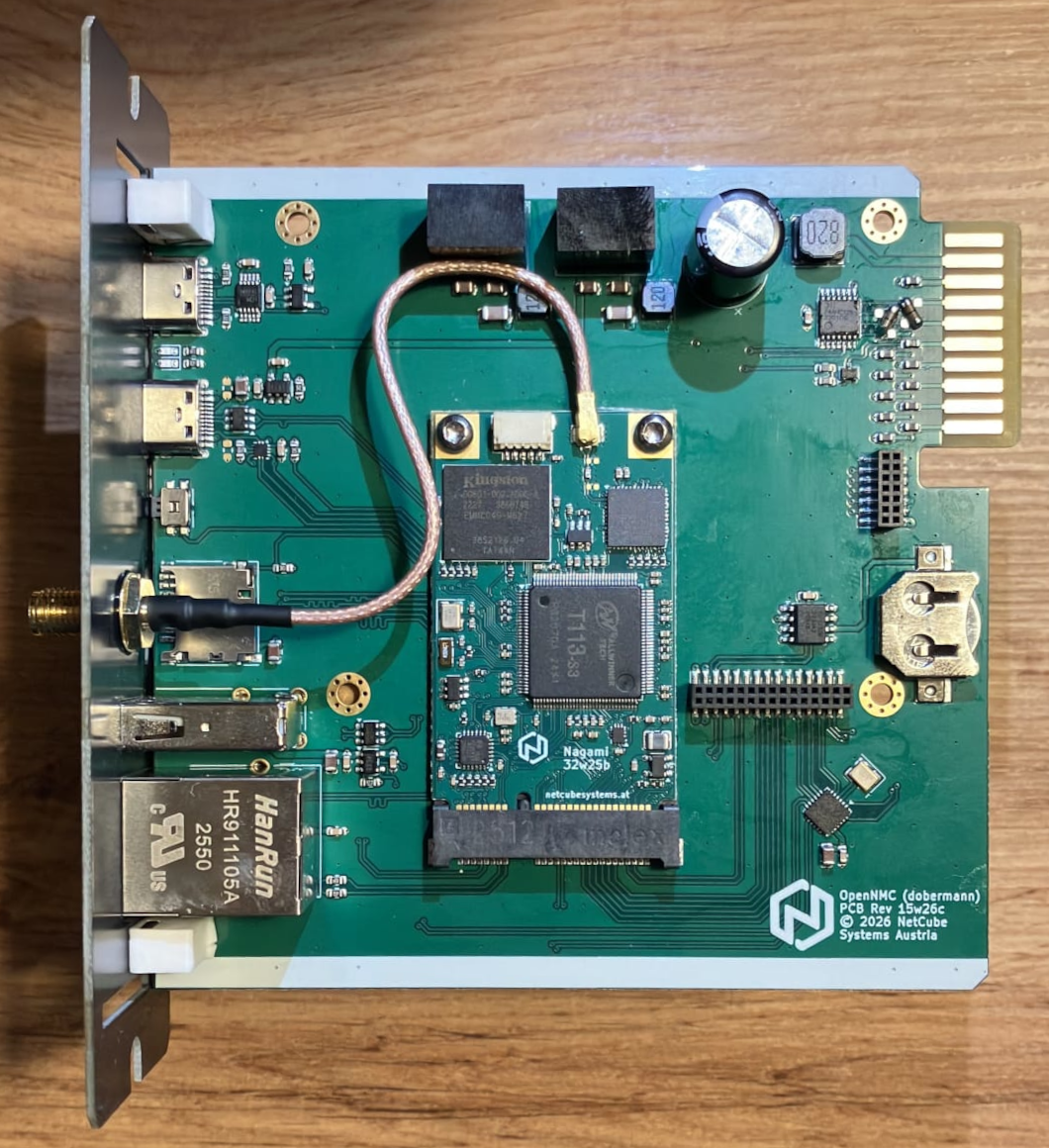
Viewed from above, with the front panel on the left side of the board, the GPIO socket is the horizontal 2x15 connector and the CARD socket is the vertical 2x8 connector above it.
In that orientation, pin 1 of GPIO is on the top-left of the socket, and pin 1 of CARD is on the bottom-left of the socket.
The screws are located at the outer edges of the board, away from the connector pair.
GPIO Header
| Description | Label | Pin | Pin | Label | Description |
|---|---|---|---|---|---|
| Power | +5V | 2 | 1 | +5V | Power |
| Power | +3.3V | 4 | 3 | +3.3V | Power |
| I2C bus | I2C_SCL |
6 | 5 | I2C_SDA |
I2C bus |
| GPIO | GPIO_PG12 |
8 | 7 | GPIO_PG13 |
GPIO |
| GPIO | GPIO_PB4 |
10 | 9 | GPIO_PB5 |
GPIO |
| Ground | GND | 12 | 11 | GND | Ground |
| SPI bus | SPI_MOSI |
14 | 13 | SPI_MISO |
SPI bus |
| SPI bus | SPI_CLK |
16 | 15 | SPI_CS |
SPI bus |
| SPI or GPIO | SPI_HOLD / GPIO |
18 | 17 | SPI_WP / GPIO |
SPI or GPIO |
| Ground | GND | 20 | 19 | GND | Ground |
| USB 0 | USB_P0_D+ |
22 | 21 | USB_P0_D- |
USB 0 |
| USB 1 | USB_P1_D+ |
24 | 23 | USB_P1_D- |
USB 1 |
| USB 2 | USB_P2_D+ |
26 | 25 | USB_P2_D- |
USB 2 |
| Control | nUSB_OC |
28 | 27 | nVBUS_EN |
Control |
| Ground | GND | 30 | 29 | GND | Ground |
Keep the load on the +5V and +3.3V pins low. If an extension needs more than about 100 mA, derive the required rails from CARD +24V instead.
CARD Header
The SmartSlot edge connector is documented on SmartSlot Pinout.
| Description | Label | Pin | Pin | Label | Description |
|---|---|---|---|---|---|
| Secondary UART | CardEdge Pin 12 |
2 | 1 | CardEdge Pin 7 |
Secondary UART |
| SmartSlot supply | +24V | 4 | 3 | +24V | SmartSlot supply |
| Auxiliary SmartSlot | CardEdge Pin 19 |
6 | 5 | CardEdge Pin 20 |
Auxiliary SmartSlot |
| Auxiliary SmartSlot | CardEdge Pin 17 |
8 | 7 | CardEdge Pin 18 |
Auxiliary SmartSlot |
| CAN bus | CardEdge Pin 15 |
10 | 9 | CardEdge Pin 16 |
CAN bus |
| Power control | CardEdge Pin 13 |
12 | 11 | CardEdge Pin 14 |
Power control |
| Battery sense | CardEdge Pin 5 |
14 | 13 | CardEdge Pin 10 |
Battery sense |
| Ground | GND | 16 | 15 | GND | Ground |
Intended Use
This connector is the primary route for:
- board-specific service hardware
- external sensors
- maintenance fixtures
- future product expansions